You too can be like Foxy and the Hound from SplatBuddies, and capture balloon splats like a pro. Alls ya need is an Ar-du-eee-no, a pee-zo, and a bit of the ol' know-how.
Yeah, alright, a few resistors, a zener diode, and a couple of optocouplers thrown in. And maybe an OLED display and a joystick if you're the adventurous kind. Oh, and a fancy camera able to do long exposures, and a reasonably flash speedlight (A.K.A. a flashy thing) with a remote trigger port, which is found on most half decent speedlights on the market.
And balloons, right? Lots of balloons, because this shit's fun.
Piezos, which are generally used to make beep-bleep-blarp sounds in electronic gadgets, generate a voltage when banged. Who knew? Yeah, I might have. They also generate an eensy-weensy voltage when touched ever so slightly, and even this slight touch is easily detectable by a reasonable analogue to digital converter.
Just a bloody touch, right? Too right!
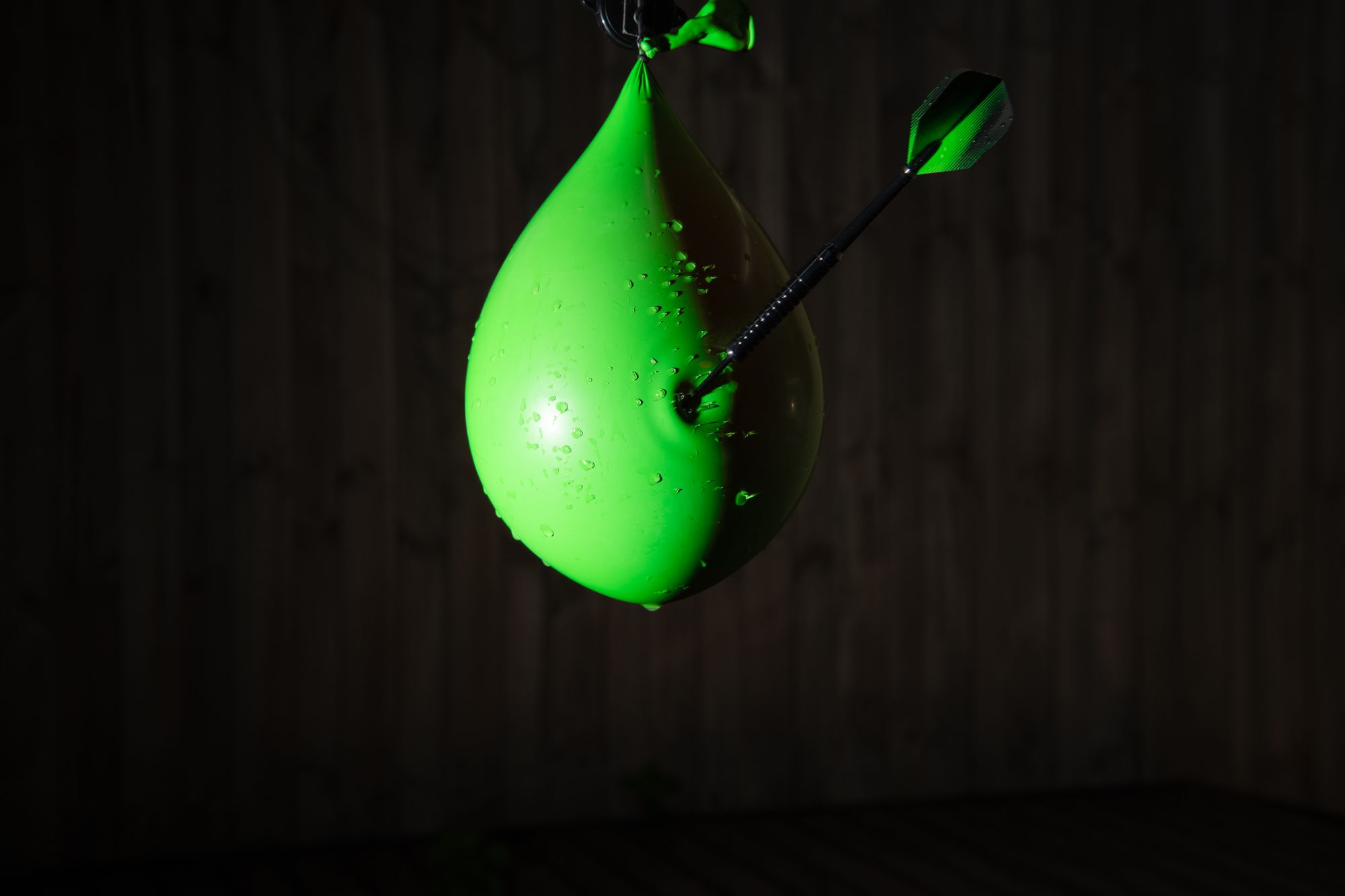
Well, smack a balloon in the vicinity, and you've got one helluva touch, ain't ya? So therein lies the design principle behind the balloon splat detector, with the aim being to catch the slightest movement in the narrowest of timeframes with a microcontroller, and by so doing set off an almighty flash from your speedlight as a result, and Bam! There's your balloon exploding shot.
Building it
The circuitry is super simple, and the parts required mostly cheap.
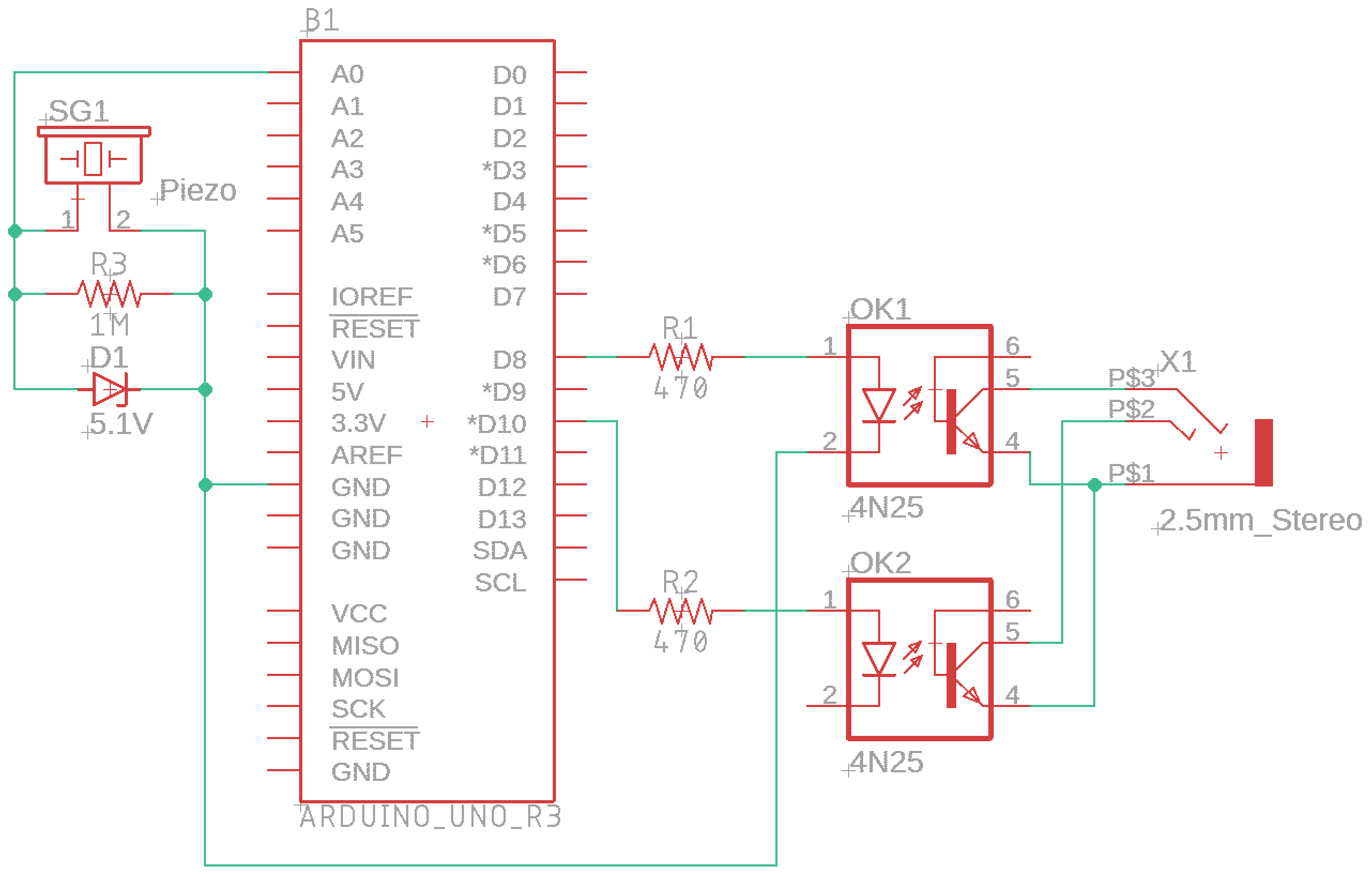
In building a home cooked trigger to fire a flash or your camera, it's always advisable to safeguard your expensive photoing gear by isolating it electrically. Optocouplers are perfect for this purpose, and two are needed to build a complete trigger - one for the focus, and one for the shutter, both pressed together. (If you just want to use this trigger only for a flash then only one is needed. But heck, they're only a couple of bucks apiece, so you might as well do it properly and give your trigger more possible uses in future.)
And speaking of protection, a zener diode is needed to protect your Arduino micro from loud balloon bangs. After all, that little piezo sensor you're packing can pack quite a punch when thumped, so don't skimp on a little 5.1 volt protection, yeah? Slight touches might be millivolts, but a thump can blow a microcontroller input to microcontroller heaven before you can say, "Why my flash no flash no more?"
Toss in a few resistors, a 2.5mm stereo jack, and Bob's your uncle.
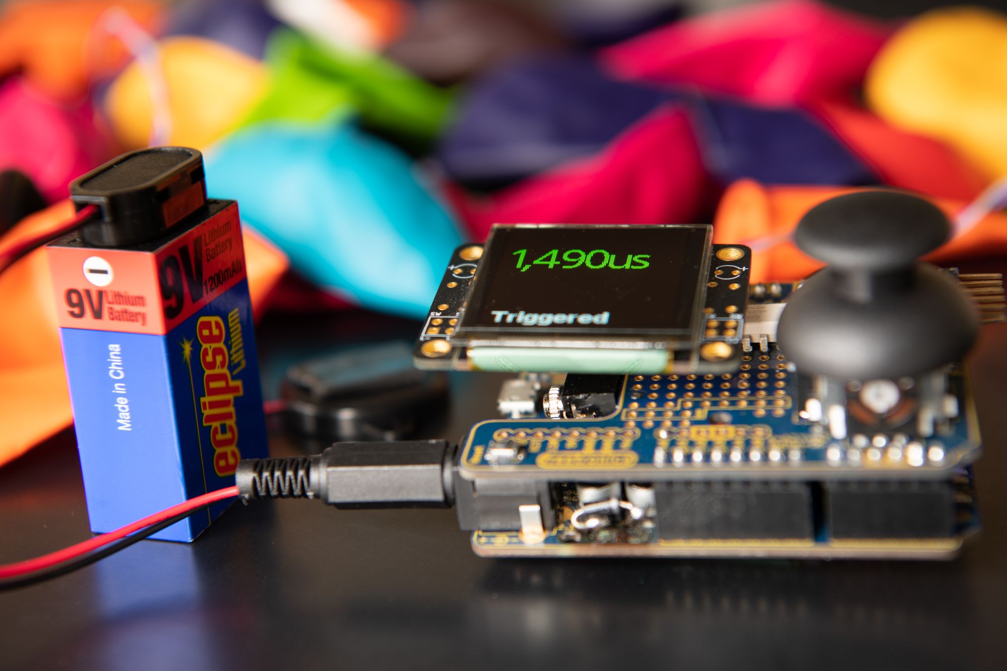
Oh, and the OLED display and joystick? Yeah, because. Because nerd and need a user interface to fine tune splat timing without reaching for a laptop. They also add a nerd factor that is just ... satisfying, whilst being convenient to slow down the action when your balloons are being photo'd too soon, or to speed it up when you want to fine tune the exact moment that shit hits. The display used in this build is the most expensive part of the whole trigger, and other far cheaper options are available. For me, it was what I had in my electronics gadget box, so that's what I used.
The circuit
Parts
- Freetronics Eleven (Arduino Uno compatible micro)
- Freetronics 128x128 Pixel OLED Module
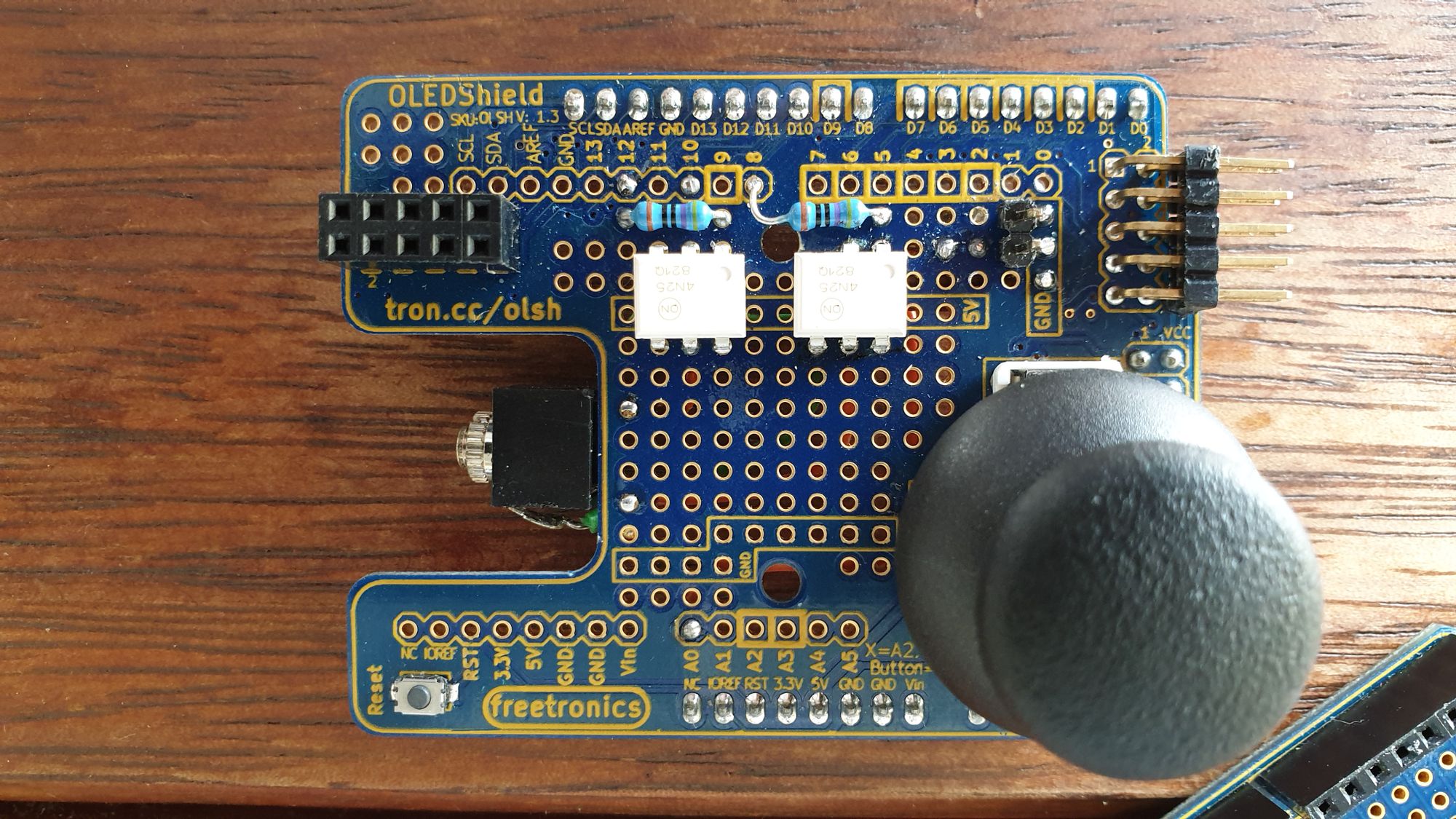
- Freetronics OLED Shield LCD Adapter
- 2 x 4N25 optocouplers (Jaycar ZD1928)
- 2 x 470 ohm resistors (nerd math says 380 ohm, but ah, well, approx above is good)
- 1 megaohm resistor (or above, again, kinda engineer whatever-ish)
- 5.1V zener diode (Jaycar ZR1403)
- 2.5mm stereo jack (Jaycar PS0107)
- Piezo element (I used Jaycar AB3442. You can't use a 'buzzer', like those used to go beep-beep-beep when trucks reverse...)
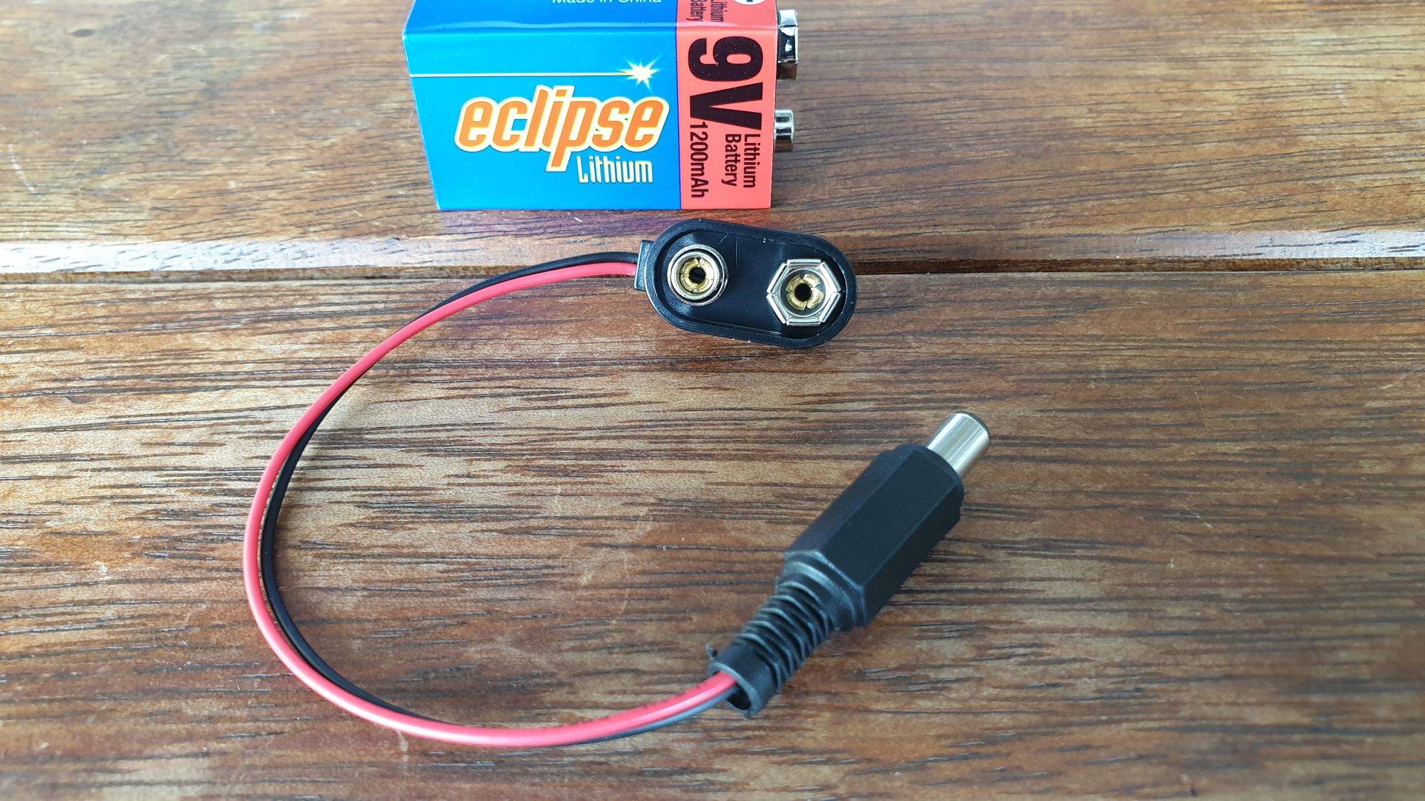
- Wire and shrink wrap, 9V battery
- 9V battery snap and a 5.5mm/2.1mm plug (Jaycar PH9233 & PP0509 to do it yourself with a soldering iron, or they sell a pre-assembled cable with the snap and plug on a 30cm cable, which is slightly more expensive by a couple of bucks PH9251)
Freetronics have an online store where you can get their gear. I prefer their stuff over the Duinotech UNO-compatible boards that the local Jaycar sell, mostly because Freetronics use micro USB, giving clearance for the OLED Shield above it not to contact the clunky USB Type B socket that Duinotech and the genuine Arduino UNOs use (and everyone has micro USB cables lying around these days, so duh! Type B USB is so 1990s, and dead to even us 50-somethings, who now use USB C). Jaycar also no longer sell the 128x128 OLED modules that are compatible with the Shield, so they're only available online from the source. But Jaycar do still sell the OLED Shield in store that is designed for it ... but if you're not stocking the OLED to suit... why? Probably because it has a JOYSTICK! And who doesn't like a joystick?
Schematic
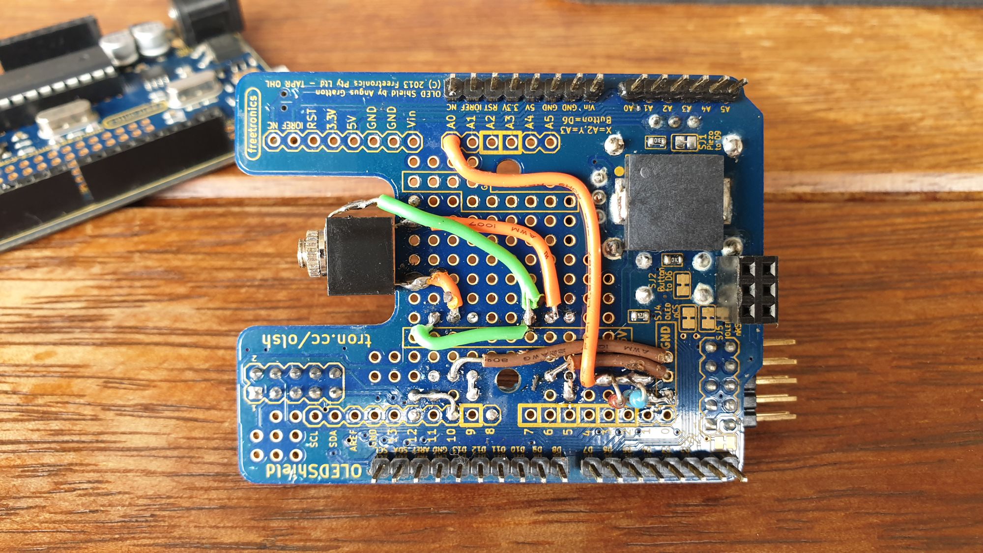
The build
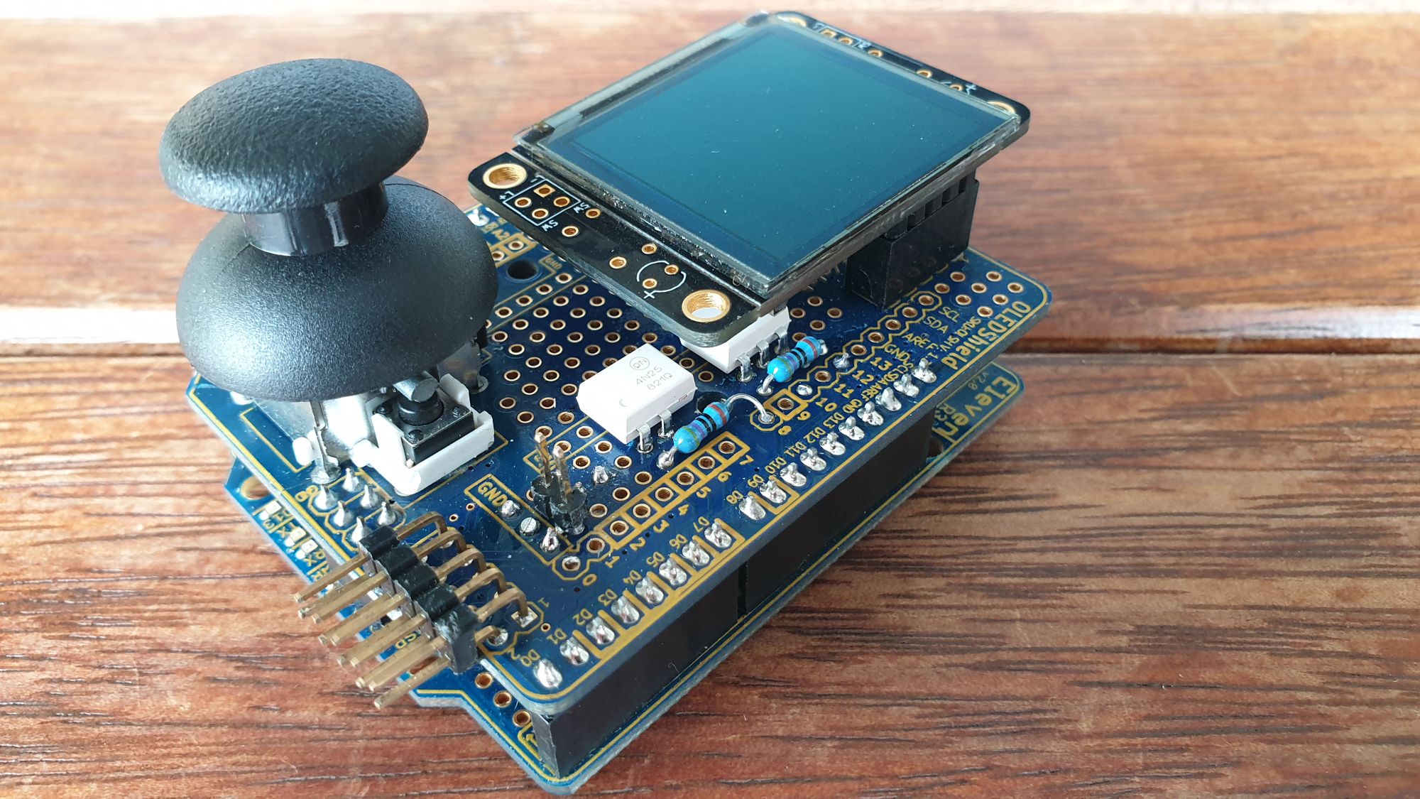
Assembly
The Freetronics OLED Shield Adapter incorporates a small amount of space that can hold the optocouplers and other components, as well as providing a handy connector for the display and joystick (!) already installed. If you get the right kind of 2.5mm stereo jack it can be made to fit, too.
Extra stuff
I strung the piezo at the end of just under a metre extension, with a small plug to make it detachable from the OLED Shield. You don't have to, though. Just make sure you get the polarity right, because piezos are polarised.
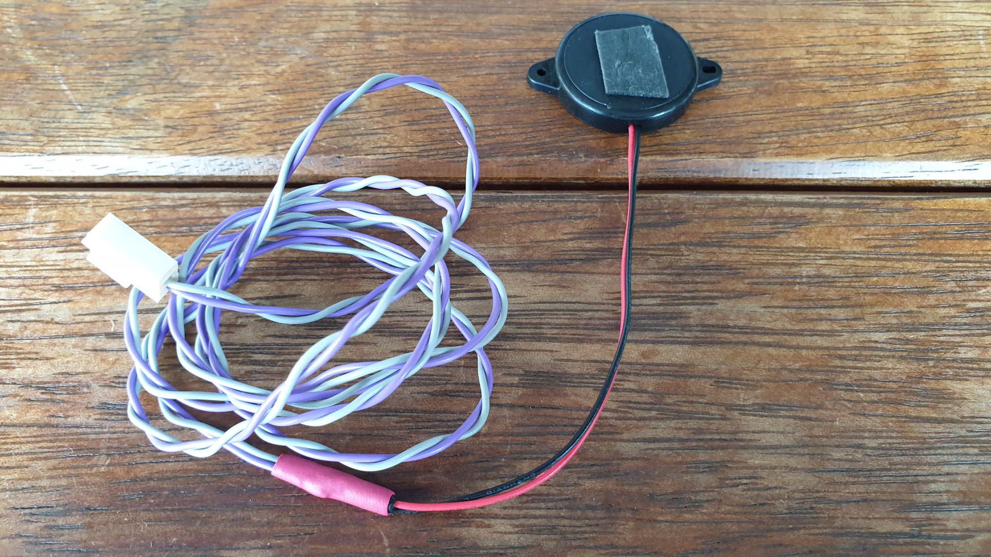
Add a power cord, and voila!
The best part of using the OLED Shield is that there is absolutely no wiring to be done for the joystick and display. Just plug that in, and we're good to code it.
The coding
Using an Arduino for this trigger means a great free IDE can be used for coding. Grab it at https://www.arduino.cc/en/main/software.
Also grab the FTOLED Library from Freetronics and install it in your library directory (see their quick start guide for details).
Here's my sketch:
//#define SERIALDEBUG 1

#include <EEPROM.h>
#include <SPI.h>
#include <SD.h>
#include <FTOLED.h>
#include <fonts/Arial_Black_16.h>
#include <fonts/Droid_Sans_36.h>

// Mode:
//  1 = Vibration sensor
const byte mode = 1;
const byte DutyTime = 30; // milliseconds to trigger the shutter button for

// Pin uses
const byte pin_focus = 8;
const byte pin_shutter = 10;
const byte pin_led = 13;
const byte analog_piezoIn = A0; // piezo on analog pin 0
const byte analog_threshold = A4; // vibration threshold adjust on analog pin 4

const byte pin_cs = 7;
const byte pin_dc = 2;
const byte pin_reset = 3;
const byte pin_button = 6;
const byte pin_piezo = 9;
const byte analog_x = A2;
const byte analog_y = A3;

byte delayUnits = 0;
int shutterDelay = 1500;
int threshold = 7;
const int alarmTime = 2000; // Number of milliseconds to keep the vibration alarm high and prevent multiple triggering

bool setActive = false;
bool setUpdate = true;
unsigned long lastSetMillis = millis();
unsigned long displayMillis = millis();
bool timeoutRunning = true;
const unsigned long displayTimeout = 3000;

byte ledState = LOW;
boolean bAlarm = false;
unsigned long lastDetect;

OLED oled(pin_cs, pin_dc, pin_reset);

void setup() {
  #if defined(SERIALDEBUG)
  Serial.begin(9600);
  #endif
  oled.begin();

  delayUnits = EEPROM.read(1);
  if ((delayUnits < 0) || (delayUnits > 1)) delayUnits = 0;
  shutterDelay = (EEPROM.read(3) << 8) | EEPROM.read(2);

  pinMode(pin_focus, OUTPUT);
  digitalWrite(pin_focus, LOW);
  pinMode(pin_shutter, OUTPUT);
  digitalWrite(pin_shutter, LOW);
  pinMode(pin_button, INPUT);
  pinMode(pin_piezo, OUTPUT);

  switch(mode) {
    case 1:
      analogReference(INTERNAL);
      pinMode(pin_led, OUTPUT);
      #if defined(SERIALDEBUG)
      Serial.println(F("Ready to receive vibration trigger"));
      #endif
      break;
  }
}

void interface() {
  int dx;
  int dy;
  const int dt[6] = { 0, 500, 300, 100, 12, 0 };
  char setMsg[11] = "";
  char unitS[3];
  OLED_Colour updateColour;

  if(setActive) {
    dx = map(analogRead(analog_x), 0, 1024, 2, -3);
    if (dx < 0) dx++; // stop wobbles around centre point
    if (dx > 0) dx--;
    dy = map(analogRead(analog_y), 0, 1024, 6, -7);
    if (dy < 0) dy++; // stop wobbles around centre point
    if (dy > 0) dy--;
    if ((dy != 0) &&(millis() - lastSetMillis >= dt[abs(dy)])) {
      switch (dy) {
        case 5:
        case -5: dy *= 2; break;
      }
      shutterDelay += dy;
      lastSetMillis = millis();
      setUpdate = true;
    }
    if (dx != 0) {
      switch (dx) {
        case 1: if (delayUnits == 1) { delayUnits = 0; setUpdate = true; } break;
        case -1: if (delayUnits == 0) { delayUnits = 1; setUpdate = true; } break;
      }
    }
    if (digitalRead(pin_button) == LOW) {
      setActive = false; setUpdate = true; analogReference(INTERNAL); analogRead(analog_piezoIn); while (digitalRead(pin_button) == LOW);
      noTone(pin_piezo);
      tone(pin_piezo, 880);
      delay(50);
      tone(pin_piezo, 90, 20);
      // Save the configured values
      EEPROM.update(1, delayUnits);
      EEPROM.update(2, shutterDelay & 0xFF);
      EEPROM.update(3, (shutterDelay >> 8) & 0xFF);
      displayMillis = millis();
      timeoutRunning = true;
    }
  } else {
    if (digitalRead(pin_button) == LOW) {
      noTone(pin_piezo);
      tone(pin_piezo, 900);
      delay(50);
      tone(pin_piezo, 90, 20);
      setActive = true; setUpdate = true; analogReference(DEFAULT); while (digitalRead(pin_button) == LOW);
    }
  }

  if (timeoutRunning && ((millis() - displayMillis) > displayTimeout)) {
    updateColour = BLACK;
    timeoutRunning = false;
    setUpdate = true;
  } else {
    updateColour = WHITE;
  }

  if (setUpdate) {
    oled.selectFont(Arial_Black_16);
    oled.drawString(6,104,F("Shutter delay:"),updateColour,BLACK);
    oled.selectFont(Droid_Sans_36);
    switch (delayUnits) {
      case 0: strcpy(unitS,"us"); break;
      case 1: strcpy(unitS,"ms"); break;
    }
    if (shutterDelay >= 1000)
      snprintf(setMsg,sizeof(setMsg),"%d,%03d%s  ",shutterDelay/1000,shutterDelay%1000,unitS);
    else
      snprintf(setMsg,sizeof(setMsg),"%d%s  ",shutterDelay,unitS);
    oled.drawString(6,66,setMsg,setActive ? GREEN:updateColour,BLACK);
    setUpdate = false;
  }
}

void vibrationTest() {
  //threshold = analogRead(analog_threshold);
  int maxReading = 0;
  int sensorReading;    // Raw value read from the sensor pin
  for (int x = 0; x < 5; x++) { // multiple A/D readings
    sensorReading = analogRead(analog_piezoIn);
    if (sensorReading > maxReading) {
      maxReading = sensorReading; // store peaks
    }
  }

  // if the sensor reading is greater than the threshold then fire the trigger
  if (maxReading >= threshold) {
    if (!ledState) {
      //  Slight pause
      switch (delayUnits) {
        case 0: delayMicroseconds(shutterDelay); break;
        case 1: delay(shutterDelay); break;
      }
      // Fire the shutter
      digitalWrite(pin_focus, HIGH);
      digitalWrite(pin_shutter, HIGH);
      // LED on
      ledState = 1;
      digitalWrite(pin_led, ledState);
      // Note the occurrence
      #if defined(SERIALDEBUG)
      Serial.print(F("Trigger "));
      Serial.print(maxReading);
      Serial.print(F(" "));
      Serial.print(threshold);
      Serial.print(F(" "));
      float piezoV = maxReading / 1024.0 * 5.0;
      Serial.print(piezoV);
      Serial.print(F("V\n"));
      #endif
      // Reset the shutter after slight pause
      delay(DutyTime);
      digitalWrite(pin_shutter, LOW);
      digitalWrite(pin_focus, LOW);
      bAlarm = true;
      lastDetect = millis();
      oled.selectFont(Arial_Black_16);
      oled.drawString(6,0,F("Triggered"),WHITE,BLACK);
    }
  } else {
    // Reset and rearm
    if(((millis() - lastDetect) > alarmTime) && ledState) {
      digitalWrite(pin_led, LOW);
      ledState = 0;
      oled.drawString(6,0,F("         "),BLACK,BLACK);
    }
  }
}

void loop() {
  interface();

  // The switch is used to select which mode the board is sensing in.
  // My full sketch incorporates modes for infrared, and also microphone sensing.
  // Mode is set in a constant in this sketch, but that could be incorporated into
  // the user interface to switch modes on the fly (like with a long press of the
  // joystick button).

  if (!setActive) switch(mode) {
    case 1: vibrationTest(); break;
  }
}
The photoing
Foxy and I use our cameras in manual mode at ISO 100, f/11 and a shutter speed of 2 seconds. The environment is dark, allowing the light of the triggered flash to freeze the splat action during the long exposure.
Trigger the camera with a remote, then chuck something pointy at your balloon, with the piezo stuck to something close, and... Bam!
Joystick interface
The joystick can be used to set a delay from when a vibration is sensed to when the trigger is used to fire the flash or camera shutter.
Push down the stick to set programming mode (the whole thing is a button), then use the up/down Y axis to increase or decrease the delay. Using the left/right X axis switches between microseconds and milliseconds, allowing considerable delay flexibility.
To exit programming mode, push the joystick down again.
The delay is stored in EEPROM memory on the Arduino, saving the setting for the next time the trigger is powered up.
Messing about
We've played with various speedlight settings, but the current favourite is manual 1/8 for the flash, and f/11 for the camera, with the speedlight positioned just under a metre away from the target. Less flash intensity would be better, because it's faster, but opening the aperture messes with good depth of field. Putting the flash closer is an option, but it's gonna get wet. Of course, you could up the ISO, sacrificing clarity.
We've had great success with anywhere from zero trigger delay to ~1,500 microseconds.
I fucken love this shit.